B10A2:00 [PCM (SKYACTIV-G)]
id9902i0106900
-
Note
-
• To determine the malfunctioning part, proceed with the diagnostics from [Function Inspection Using M-MDS].
Details On DTCs
| System malfunction location |
Vehicle collision determination system: Vehicle collision |
|
|---|---|---|
|
Detection condition
|
Determination condition
|
• The PCM detects a vehicular collision from the collision signal received from the SAS control module.
|
|
Precondition
|
• Not applicable
|
|
|
Drive cycle
|
• 1
|
|
|
Self-test type
|
• CMDTC self-test
|
|
|
Sensor/unit used
|
• PCM
|
|
|
Fail-safe
|
• Stops the fuel injection control.
• Stops the fuel pump control.
• Stops the ignition control.
• Stops the engine coolant fan control.
• Performs vehicle speed restriction according to low battery voltage, and activates Auto P function at a vehicle speed of 5 km/h {3 mph} or less.
|
|
|
Vehicle status when DTCs are output
|
• Stops the fuel pump pre-operation when the ignition is switched ON.
• Delay in starter operation at cranking position (maximum 1.2 s)
|
|
|
Possible cause
|
• Vehicle is involved in collision (collision signal from SAS control module is received)
• SAS control module malfunction
• PCM malfunction
|
|
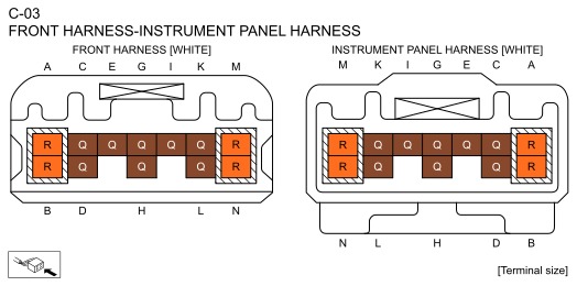
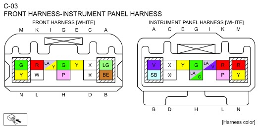
System Wiring Diagram
• Not applicable
Function Explanation (DTC Detection Outline)
• During a collision, the SAS control module sends a collision signal to the PCM via the CAN signal. The PCM stores a DTC if it receives a collision signal.
• This DTC does not indicate a part malfunction. It indicates operation of failsafe from safety assurance during a vehicle collision.
bda2zd00001583
|
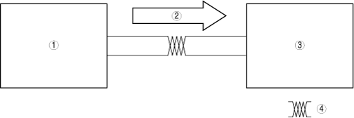
|
1
|
SAS control module
|
|
2
|
Collision signal
|
|
3
|
PCM
|
|
4
|
HS-CAN
|
Repeatability Verification Procedure
1. Switch the ignition ON and leave for 5 s.
2. Clear the DTC recorded in the memory using the M-MDS.(See: CLEARING DTC.)
3. Switch the ignition OFF, switch the ignition back ON, and leave for 5 s.
4. Using the M-MDS, verify that DTC U0151:00 is not displayed.(See: DTC INSPECTION.)
PID Item/Simulation Item Used In Diagnosis
• Not applicable
Function Inspection Using M-MDS
| Step |
Inspection |
Results |
Action |
|---|---|---|---|
|
1
|
PURPOSE: VERIFY VALID REPAIR INFORMATION OR SERVICE INFORMATION
• Verify if there is valid servicing information.
• Is there valid servicing information?
|
Yes
|
Repair or perform diagnostics according to valid servicing information.
• If the malfunction is not resolved, go to the next step.
|
|
No
|
Go to the next step.
|
||
|
2
|
PURPOSE: RECORD VEHICLE STATUS WHEN DTC WAS DETECTED TO UTILIZE WITH REPEATABILITY VERIFICATION
• Record the freeze frame data/snapshot data.
|
—
|
Go to the next step.
|
|
3
|
PURPOSE: VERIFY IF SYMPTOM IS NORMAL OPERATION DUE TO VEHICLE COLLISION
• Ask customer about vehicle collision experience.
• Has the vehicle in for servicing been involved in a collision in which the air bag is deployed?
|
Yes
|
Explain to the customer that the DTC is recorded as a result of a vehicle collision.
Go to the troubleshooting procedure to perform the procedure from Step 1.
|
|
No
|
Go to the next step.
|
||
|
4
|
PURPOSE: VERIFY SAS CONTROL MODULE DTCs
• Perform the DTC inspection for the SAS control module. (See DTC INSPECTION.)
• Is a DTC displayed?
|
Yes
|
Go to the applicable DTC inspection.
(See DTC TABLE [SAS].)
Go to the troubleshooting procedure to perform the procedure from Step 1.
|
|
No
|
Go to the troubleshooting procedure to perform the procedure from Step 1.
|
Troubleshooting Diagnostic Procedure
Intention of troubleshooting procedure
• Step 1
• Repair completion verification
-
― Verify that the primary malfunction is resolved and there are no other malfunctions.
| Step |
Inspection |
Results |
Action |
|---|---|---|---|
|
1
|
PURPOSE: PERFORM DTC INSPECTION AND VERIFY IF MALFUNCTIONING LOCATION IS PCM
• Install/connect the part removed/disconnected during the troubleshooting procedure.
• Clear the DTC recorded in the memory. (See CLEARING DTC.)
• Replicate the vehicle conditions at the time the DTC was detected using the following procedure.
• Perform the DTC inspection for the PCM. (See DTC INSPECTION.)
• Is the same DTC displayed?
|
Yes
|
Refer to the CAN (controller area network) malfunction diagnosis flow to inspect for a CAN communication error.
If the CAN communication is normal, perform the diagnosis from Step 1 again.
• If the malfunction is not resolved, replace the PCM, then go to the next step. (Refer to [PCM REMOVAL/INSTALLATION] in workshop manual.)
|
|
No
|
Go to the next step.
|
||
|
Repair completion verification 1
|
PURPOSE: VERIFY IF OTHER DTCs OCCURRED SIMULTANOUSLY
• Perform the DTC inspection. (See DTC INSPECTION.)
• Are other DTCs displayed?
|
Yes
|
Go to the applicable DTC inspection.
|
|
No
|
DTC troubleshooting completed.
|