B00C5:1D [SAS]
id9902k0806800
Details On DTCs
| System malfunction location |
Passenger-side seat track position sensor circuit current out of range |
|
|---|---|---|
|
Detection condition
|
Determination conditions
|
• Passenger-side seat track position sensor malfunction
• Malfunction in wiring harness between passenger-side seat track position sensor and SAS control module.
|
|
Preconditions
|
• Not applicable
|
|
|
Determination period
|
• Not applicable
|
|
|
Fail-safe
|
• Not applicable
|
|
|
Vehicle status when DTCs are output
|
• Not applicable
|
|
|
Possible cause
|
• Passenger-side seat track position sensor connector malfunction
• Malfunction in wiring harness (including connector/terminal) between passenger-side seat track position sensor and SAS control module
• Passenger-side seat track position sensor malfunction
• SAS control module malfunction
|
|
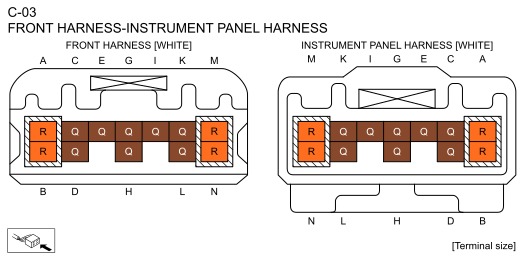
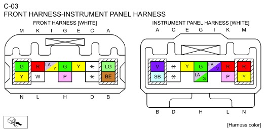
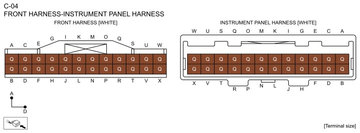
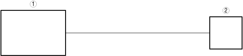
System Wiring Diagram
bda2zd00000547
|
|
1
|
SAS control module
|
|
2
|
Passenger-side seat track position sensor
|
Function Explanation (DTC Detection Outline)
• Not applicable
Repeatability Verification Procedure
• Not applicable
Function Inspection Using M-MDS
• Not applicable
Troubleshooting Diagnostic Procedure
| Step |
Inspection |
Results |
Action |
|---|---|---|---|
|
1
|
PURPOSE: INSPECT PASSENGER-SIDE SEAT TRACK POSITION SENSOR CIRCUIT
• Display the SAS control module PID [SEAT_TRACK_STAT] using the M-MDS. (See PID/DATA MONITOR INSPECTION.)
• Is the seat track position sensor circuit normal?
|
Yes
|
Refer to the CAN (controller area network) malfunction diagnosis flow to inspect for a CAN communication error.
If the CAN communication is normal, perform the diagnosis from Step 1 again.
• If the malfunction is not resolved, replace the SAS control module and perform repair completion verification 2. (Refer to [SAS CONTROL MODULE REMOVAL/INSTALLATION] in workshop manual.)
|
|
No
|
Go to the next step.
|
||
|
2
|
PURPOSE: INSPECT PASSENGER-SIDE SEAT TRACK POSITION SENSOR CONNECTOR
• Switch the ignition/main power OFF.
• Disconnect the negative battery terminal/negative lead-acid battery terminal and wait for 1 min or more. (Refer to [NEGATIVE BATTERY TERMINAL DISCONNECTION/CONNECTION] in workshop manual.)
• Disconnect the passenger-side seat track position sensor connector. (Refer to [SEAT TRACK POSITION SENSOR REMOVAL/INSTALLATION] in workshop manual.)
• Inspect the passenger-side seat track position sensor connector.(Corrosion, damage, and disconnected pins)
• Are the connector and terminal normal?
|
Yes
|
Go to the next step.
|
|
No
|
Repair or replace the malfunctioning location and perform repair completion verification 1.
|
||
|
3
|
PURPOSE: INSPECT FOR MALFUNCTION IN WIRING HARNESS (INCLUDING CONNECTOR/TERMINAL) BETWEEN PASSENGER-SIDE SEAT TRACK POSITION SENSOR AND SAS CONTROL MODULE
• Disconnect the following connectors.
• Inspect the applicable circuit. (See CIRCUIT INSPECTION.) (See CONNECTOR INSPECTION.)
• Is the circuit normal?
|
Yes
|
Replace the passenger-side seat track position sensor and perform repair completion verification 1.
|
|
No
|
Repair or replace the malfunctioning location and perform repair completion verification 1.
|
||
|
Repair completion verification 1
|
PURPOSE: VERIFY IF VEHICLE IS REPAIRED
• Switch the ignition/main power OFF.
• Disconnect the negative battery terminal/negative lead-acid battery terminal and wait for 1 min or more. (Refer to [NEGATIVE BATTERY TERMINAL DISCONNECTION/CONNECTION] in workshop manual.)
• Connect the passenger-side seat track position sensor connector.
• Connect the negative battery terminal/negative lead-acid battery terminal. (Refer to [NEGATIVE BATTERY TERMINAL DISCONNECTION/CONNECTION] in workshop manual.)
• Switch the ignition ON (engine off or on)/switch the main power ON (READY off or on).
• Clear the DTC recorded in the memory. (See CLEARING DTC.)
• Perform the DTC inspection for the SAS control module. (See DTC INSPECTION.)
• Is the same DTC displayed?
|
Yes
|
Refer to the CAN (controller area network) malfunction diagnosis flow to inspect for a CAN communication error.
If the CAN communication is normal, perform the diagnosis from Step 1 again.
• If the malfunction is not resolved, replace the SAS control module, then go to the next step. (Refer to [SAS CONTROL MODULE REMOVAL/INSTALLATION] in workshop manual.)
|
|
No
|
Go to the next step.
|
||
|
Repair completion verification 2
|
PURPOSE: VERIFY IF OTHER DTCs ARE DISPLAYED
• Perform the DTC inspection. (See DTC INSPECTION.)
• Are other DTCs displayed?
|
Yes
|
Repair or replace the malfunctioning location according to the applicable DTC troubleshooting.
|
|
No
|
DTC troubleshooting completed.
|